


This section discussed our proposed method. We designed the following five models for hybrid systems: system model, feedback model, and chaotic map generation model. We also discussed the secured models for the hybrid system and the intensity modulating and direct detection system.
System model
This study presents a new approach to community safety and privacy to address the continued problems with conventional strategies. Inadequacies, compromised security, and lack of synchronization are commonplace reasons cutting-edge strategies fail. The suggested method carries strong chaotic generation, improves safety, and handles parameter fluctuations to conquer those constraints. This paper aims to enhance network protection while maintaining green communication channels by combining HOFS with chaotic optical communication systems.
This schematic Fig. 1 depicts a system model for chaotic optical communication, which uses chaotic indicators to soundly transport facts over a community of linked components. The data supply is the first step because it components the entry necessary to generate a chaotic signal C(t) using a chaotic system. For.

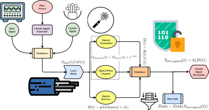
System model for chaotic optical communications.
report phrases to create a modulated sign that can be expressed as M(t) = S(t) ×C(t), the Chaotic Signals.
generates and modifies these chaotic alerts earlier than combining them with the facts. The modulated sign is.
first interfaced with the laser diode Ochannel (t) = f (M(t)) by the modulator to prepare the modulated sign for transmission through the optical transmitter. The optical signals are dispatched to the optic receiver R(t) = g(Ochannel (t)), which demodulates through the optical fiber channel and optical transmitter using Ochannel(t) = Olaser(t)e˘αL, where α is the attenuation coefficient, and Lis the length of the fiber. After the demodulation technique D(t) = R(t)/C(t), the records can be recovered using the Chaotic Pattern.
Decoding module Sdecrypted (t) = h(D(t)) to decode the chaotic alerts. At the end, the Data Sink receives the decrypted records by Data − Sink(Sdecrypted (t)) and sends them to the subsequent processing stage. This integration uses chaotic dynamics’ inherent unpredictability to improve information transmissionsecurity and privacy by using chaotic signals. This era provides a sturdy approach for transmitting encrypted information, ideal for uses that call for absolute secrecy and authenticity, combining optical communique methods with chaotic signal production. Various communications scenarios and networks may be easily accommodated using the device’s modular layout, making it scalable.
$$\:\left\\fraceF_TM\left(u\right)eu\right\=\:\frac12\left(1+j\forall\:\right)\times\:\:H_TM+\:F_PK\left(u\right)-\:\propto\:\partial\:\complement\:$$
(5)
The dynamic character is shown by the Eq. 5. It represents the delicate balancing act that occurs when different operational variables affect efficiency (\(\:eF_TM(u\)), uncertainty (\(\:eu\)), and overall effectiveness of the system \(\:1+j\forall\:\), \(\:H_TM\), and \(\:F_PK\left(u\right)\). It can optimize industrial processes while guaranteeing safety and sustainability by adaptively managing these variables through integrating logic \(\:\propto\:\partial\:\complement\:\:\).
$$\:I_2\left(\propto\:\right)=fyq\:[k\:\times\:\:\frac12+\:\:C_1\left(\forall\:-\partial\:_0)^2\right]+\:\frac1fG\left(1+2t\right)$$
(6)
The Eq. 6 depicts the interplay of several system variables \(\:I_2\left(\propto\:\right)\). In this context, \(\:fyq\) and \(\:C_1\left(\forall\:-\partial\:_0)^2\right]\) represents certain criteria for performance that are affected by external factors \(\:fG\) and internal factors (\(\:1+2t\)). The exponential terms show ways the Non-Deterministic Dynamic Capacity Model Framework (N-DMCF) may improve safety and productivity using controlled variation by dynamically adjusting to these variances.
$$\:F_qu\left(u\right)=\:\:F_RT+u\:\left(fyq\right)+\:\:\left[k\partial\:L_mp(\forall\:-\partial\:_p)\right]$$
(7)
Moreover, the Eq. 7 represents the change in the decision variable \(\:F_qu\left(u\right)\). Here, the starting decision state is denoted by \(\:F_RT\), and the universal, process-specific, and global uncertainties are represented by \(\:u\:\left(fyq\right)\), \(\:k\partial\:L_mp(\forall\:-\partial\:_p)\) respectively.
$$\:\left\F_w3\left(u\right)\right\=n\:\left(u\right)\times\:F_out1+\left[1-n\left(u\right)\right]F_out2+\:F_t1\left(r\right)+\left(u+1\right)$$
(8)
Equation 8 shows the connection between KPIs. In this context, process parameters \(\:F_w3\left(u\right)\) impact performance metrics \(\:n\:\left(u\right)\) and \(\:F_out1\). The system’s reaction to changing operational demands \(\:1-n\left(u\right)\) and time-related factors \(\:F_out2\) is underscored by the expressions \(\:F_t1\left(r\right)+\left(u+1\right)\).
Feedback model
This section discussed the chaotic optical communication system’s feedback model, illustrated in Fig. 2. The process starts with creating chaotic signals and continues with data input into the Chaos Signal Generator. The data and these chaotic signals are modulated in the modulator before the Optical Transmitter’s Laser Diode turns them into optical signals. The Optical Receiver demodulates optical signals after they have been sent via the Optical Fiber Channel. After the demodulation technique, the statistics may be recovered using the module to decode the chaotic alerts. The Data Sink also processes and analyzes the statistics simultaneously. The HOFS-COCS, which improves security and resilience, makes this system unique. The HOFS-COCS uses photonic and visual feedback strategies to regulate parameter fluctuations and assure sturdy chaos creation. Data integrity and confidentiality are critical in communication systems, leading to better synchronization and secure message transport. The device’s general balance and dependability are better through comment loops that alter optoelectronic and optical characteristics. Incorporating chaotic optical verbal exchange into a feedback device boosts overall performance, flexibility, and protection. This all-encompassing approach of steady verbal exchange gives an encouraging answer for uses that necessitate reliable and fairly secure statistics transmission.

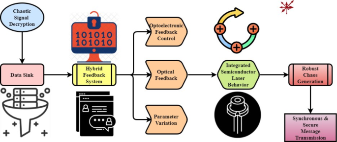
Feedback model for chaotic optical communications.
$$\:F_u\left(u\right)=\:G^-1\left(G\:\left[F_q2\left(u\right)\right]\right)+\:G_2\left(u+1\right)+\:\:\left(k-mn\right)$$
(9)
The output variable \(\:F_u\left(u\right)\:\)in respect to different influencing factors that are described by the equation \(\:G^-1\left(G\:\left[F_q2\left(u\right)\right]\right)\). A performance level is represented by \(\:u+1\), a dynamic adjustment factor is denoted by \(\:G_2\), and a weighting parameter is denoted in this context. The variable indicates discrete operational states \(\:k-mn\), which range from adapting operational outputs to maximizing performance.
$$\:F_q3\left(u\right)=Fg_2\left(u\right)+fyq\:\left(k+\:Q_ku3\left[F\left(u-v_3\right)\right]\times\:\forall\:\right)$$
(10)
The Eq. 10 variables \(\:F_q3\left(u\right)\), \(\:Fg_2\left(u\right)\), and \(\:fyq\) represent particular conditions and uncertainties, and the variable\(\:\:Q_ku3\) represents a gradient factor affected by the operational state P. The fixed contribution of the term enhances the total result \(\:\forall\:\). The optimization of Eq. (10) Fq3(u) is performed using the objective function to improve the accuracy of network security using Algorithm 1 and 2. We also aim to minimize BER, which reflects the performance of the chaotic optical communication system. This function considers Eq. (10) parameters and evaluates their impact on overall system performance. The key parameters in Eq. (10) systematically varied within their operational ranges, including k, Qku3, and v3.
$$\:F_s\left(u\right)=\:G^-1\left\G\:\left[F_Q3\left(yu\right)\right]\right\+\:I_3\left(p\right)\}+\left(u+1\right)$$
(11)
To account for dynamic adjustments and uncertainties, the coefficients \(\:F_s\left(u\right)\)and \(\:G^-1\) in the Eq. 11\(\:F_Q3\left(yu\right)\) are used. In response to these factors \(\:I_3\left(p\right)\}\), the framework adaptively incorporates the gradient component \(\:u+1\).
$$\:BDE\:\left(\partial\:u\right)=\:\frac[y\left(u+\partial\:u\right)-y\:\left(u+\forall\:u\right)\left[y\left(z\right)-\:<y\left(z\right)>\right]]\sqrt\left[y\right(z\left)\right]+\left(y\right(z+\partial\:\forall\:\left)\right)$$
(12)
The particular efficiency levels influenced by the system parameters \(\:BDE\:\left(\partial\:u\right)\) are indicated by the Eq. 12. The \(\:y\left(u+\partial\:u\right)\) and \(\:y\:\left(u+\forall\:u\right)\left[y\left(z\right)-\:<y\left(z\right)>\right]\), which shows how sensitive the framework is to imperfections. The value of \(\:\left[y\right(z\left)\right]\) scales a basic performance measure, while the term \(\:y(z+\partial\:\forall\:)\) accounts for weighted risk uncertainty.
Chaotic map generation model
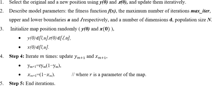
The schematic representation of the operating concept of optical communication systems based on chaos is shown in Fig. 3. One of the many existing modulation algorithms encodes information on a coherent optical carrier generated by a semiconductor laser in traditional communication. On the other hand, the suggested approach to chaos-based communications uses an optical carrier with a very broadband spectrum, typically tens of GHz, because the transmitter is just an oscillator induced to operate in the chaotic domain, for example, by providing external optical feedback. Different techniques encode the information on this chaotic carrier, which is usually based on an on-off keying bit stream. Algorithm 1 shows the pseudocode of chaotic map generation.

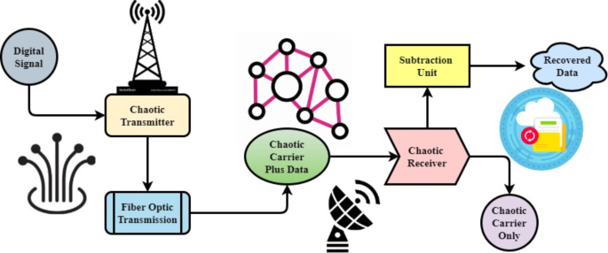
Chaotic map generation model.

One simple and efficient method is to use a separate optical modulator that is electrically motivated by the information bit-stream while the optical disorganized carrier is coupled at its input. It would be extremely difficult, if not impossible, to decipher this encoded information using traditional methods like linear filtering, frequency-domain evaluation, and phase-space reconstruction because the amplitude of the encrypted message is always kept small in comparison to the amplitude fluctuations of the chaotic carrier. The latter, in particular, depends on the chaos dynamics generation process and presupposes a very complicated chaotic carrier. A second chaotic oscillator, which can be used in the transmitter, is employed on the receiving side of the system.
$$\:\left(B_m\left(p\right)=\:\fracU_max\left(p\right)+\:U_max\left(p\right)p+qt2\right)+\:N_min-\:N_max$$
(13)
In the equation \(\:B_m\left(p\right)\), the baseline performance indicator is represented, and the variables \\(\:U_max\left(p\right)\), \(\:p+qt\), and \(\:N_min\) are the variables that contribute to the overall performance, which is then aggregated into \(\:N_max\) .
$$\:\left(U_\textmin(p-q)\right)+\left(U_\textmax\left(p-q\right)\right)=\:u_p^min-\:u_w\left(max\right)+\:v_b\left(min\right)$$
(14)
A ratio of specific variables adjusted by \(\:U_\textmin(p-q)\) and \(\:U_\textmax\left(p-q\right)\), which are affected by operational variability (\(\:u_p^min\)), is shown by the \(\:v_b\left(min\right)\). This is balanced on the Eq. 14 by a dynamic correction term and the ratio.
$$\:ERD=\:\frac1P\sum\:_j=1^q\left[P_0-\:p_m\right]+\:\left(y+1p\right)\:\times\:\left(P\left(j,k\right)\right)\times\:100\:\%$$
(15)
Equation 15 shows how different elements are interdependent on \(\:ERD\). In this case, the aggregate performance metric is denoted as \(\:\frac1P\) is adjusted by \(\:P_0-\:p_m\) and some combination of \(\:y+1p\), \(\:P\left(j,k\right)\), and \(\:100\:\%\), with \(\:j=1\) modulating the adjustment. Additionally, the symbol represents a ratio of performance to control variables.
$$\:EF_ss=\:\frac1NP\sum\:_j^P\sum\:_k=p^QR\left(j,k\right)+100\%\:\left(p-q\left(w2+1\right)\right)$$
(16)
While \(\:EF_ss\) accounts for initial circumstances, the system parameter \(\:\frac1NP\) affects the variable \(\:R\left(j,k\right)\). Both \(\:Q\) and \(\:k=p\) represent ratios that reflect the dynamics of the system and its efficacy \(\:\left(w2+1\right)\), respectively.
Secured model for hybrid system
In this section, we designed a secure combination free space/fiber optic (FSO/FO) system that uses optical chaos in various conditions shown in Fig. 4. Inside the scope of this secure communication system, the chaotic signal conceals anything included within the message through its chaos. The overwhelming majority of individuals believe that this security strategy is preferable to other methods, such as using algorithms for encryption and other relatively equivalent ways. Following the addition of the chaos signal to the message, the data analysis reveals that the transmission distance has been reduced by around one hundred kilometers. The fall in temperature takes place regardless of the meteorological conditions that are currently in effect. Under all circumstances, implementing the dual FSO channels (DFSO) leads to an increase in the hyperlink distance of around 37–40% more than previously.

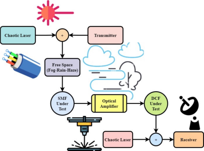
Secure model for hybrid chaotic optical communications.
$$\:s_yz=\:\frac\frac1P\sum\:_l=1^Q\left(Y_l-F\left(y\right)\right)^2+E\:\left(z\right)=\:\frac1P\sum\:_l=1^mD\left(z\right)(1-m)^2+q\left(1+p\right)$$
(17)
The variables \(\:s_yz\), \(\:1-m\), and \(\:\left(Y_l-F\left(y\right)\right)^2\) are used to represent different uncertainties and restrictions, whereas the variables \(\:D(z\) and \(\:E\:\left(z\right)\)are used to indicate certain aspects that impact the choice. Highlighting the framework’s flexibility to market dynamics, the expression \(\:q\left(1+p\right)\) indicates the system’s responsiveness to changes in both quantity and price.
$$\:E\left(y\right)=\:\frac1P\sum\:_l=1^Q\left(y_z-F\left(y\right)\right)+\left(z_l-F\left(z\right)\right)+\:\frac1v\:(u-pe)^2$$
(18)
Operational parameters are denoted by \(\:E\left(y\right)\) and critical factors impacting the outcome are represented by \(\:y_z-F\left(y\right)\)and \(\:\frac1P\). The expression \(\:z_l-F\left(z\right)\)illustrates the framework’s capacity to adapt to both external \(\:\frac1v\) and internal factors \(\:u-pe)^2\).
$$\:p_z+1=s\:\times\:g_v\left(1-z_p\right)+FRQW\:\left(\fracU_oldU_new-1\right)\times\:100$$
(19)
The variable \(\:p_z+1\) accounts for operational dynamics and efficiency, whereas the equation \(\:s\:\times\:g_v\) depicts a quantity affected by the factor \(\:1-z_p\). The term \(\:FRQW\:\left(\fracU_oldU_new-1\right)\) takes planning restrictions into consideration.
$$\:y^z+\:z_x\left(1-p\right)=a+bq+c\:heq\:\left(y\right)-y-z\:\left(p+q\right)$$
(20)
Equation 20 elements that analysis of network security is encapsulated by \(\:y^z\) and \(\:z_x\left(1-p\right)\), whereas operational dynamics and system variables are adjusted for by \(\:a+bq+c\:heq\:\left(y\right)\). Furthermore, planning limitations and changing parameters are taken into consideration by \(\:y-z\:\left(p+q\right)\).
Secured model for IM/DD system
This section designs the secured model for the intensity modulating and direct detection (IM/DD) system depicted in Fig. 5. This model is implemented on 25 km. In addition, the digital and analog domains were encrypted using phase modulator technology and digital signal processing technology, respectively. Using a sampling rate of 15 GSa/s, the encrypted signal located at the digital end was put into an Arbitrary Waveform Generation (AWG, TekAWG70002A). The photoelectric modulation process was accomplished by injecting the amplification of the analog signal into a Mach–Zehnder modulator (MZM) after it is amplified by an electric amplifier (EA). The laser’s strength and wavelengths were adjusted to be 10 dBm and 1550 nm, respectively. The signal that the MZM produced was sent to Phase Modulation (PM 1) to perform phase encryption perturbation. For the PM, the half-wave voltage was measured to be 6 V. A value of 2 was assigned to the modulation depth. which is the defining characteristic with Multiple System Operator (MSO). The chaotic circuit was responsible for the generation of the driving signal for PM 1. Following its amplification (EDFA), the modulated fiber optic signal was sent into a 25-kilometer short-wave microwave (SSMF) distance using Verband der Automobilindustrie (VDA). It is important to note that the radio frequency, or RF, signals produced by the intensity modulator and the ones generated by the phase generator are independent. As a result, there is no association between the rates produced by the intensity generator and the phase modulator with photodiode (PD). Moreover, the details of other component parameters are discussed in Table 2.

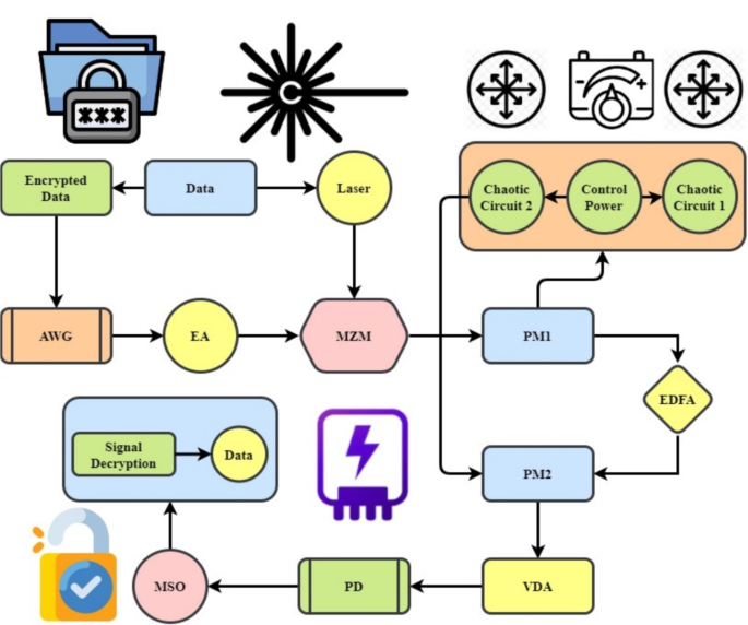
Secured model for IM/DD system.
$$\:a=\:-\:\frac1S_7D_3\times\:\left(p-q\right)+\:\frac1\left(pp+q\right)rew\:\left(z\right)-\:\frac1C_vd_f+\left(e_d\left(u+k\right)\right)$$
(21)
The analysis of synchronization is represented by the Eq. 17, \(\:a\), which takes into account \(\:pp+q\) in one part and \(\:\frac1S_7D_3\) in the other part, which takes into account the item of \(\:p-q\), \(\:rew\:\left(z\right)\), and \(\:C_vd_f\). The phrase further mitigates the effect of systems dynamics on security \(\:e_d\left(u+k\right)\).
$$\:DD=\:\frac\sum\:_p=0^q-1\left[y_j-\:\forall\:_k\right]+[z_l-Q_s](a-z)^e-1+\:\left(s+q(m-n)\right)^2$$
(22)
While \(\:y_j-\:\forall\:_k\) encompasses productivity in the sensitivity analysis, the Eq. 22\(\:DD\) acts as a multiplier for parameters connected to productivity. The expression \(\:z_l-Q_s\) represents extra factors and modifications related to productivity \(\:a-z\). Lastly, systemic impacts on production \(\:e-1\) are considered by the expression \(\:s+q(m-n)\).
$$\:Z=Nbu\:\left\edf\left(z\times\:12\left(x+1\right),\:2\right)\right\+\:\left[G_f1+.+\:H_jk2\right]=Z$$
(23)
Equation 23, in this case, \(\:edf\left(z\times\:12\left(x+1\right),\:2\right)\) denotes an analysis of robustness that is considered baseline, whereas \(\:G_f1\) takes into consideration particular environmental impacts. Additional considerations and modifications \(\:Z\) related to sustainability are included in the expression \(\:H_jk2\). Lastly, the impacts on systemic sustainability are captured by \(\:Nbu\).
$$\:J\left(p\right)=\:-\:\sum\:_p=1^eq\:\left(nj\right)log_w+Q\:\:\left(hj+kpw\right)_2+ge$$
(24)
The analysis of reliability relative to a given reference is represented by the Eq. 24\(\:J\left(p\right)\), and performance limits or deviations are adjusted for by \(\:\sum\:_p=1^eq\:\left(nj\right)log\). The expression \(\:Q\:\:\left(hj+kpw\right)_2\) represents extra factors and modifications related to performance that consider planning limitations. Finally, the impacts on systemic performance are captured by \(\:ge\). Algorithm 2 shows the Stage-by-Stage message encryption algorithm using a chaotic communication method.


An encryption algorithm using HOFS-COCS method.
link